A swash plate is a vital part of a helicopter that controls the pitch of the blades as it rotates. It's also one of the most complex pieces of a helicopter. Quad-copters reduce this complexity by removing the swash plate altogether, trading efficiency for simplicity. Instead of a swash plate you have a fixed blade and modulate the power to each. Although this makes it simpler it is a large tradeoff, one that grows exponentially as the mass of the blades increases. So how can we reduce the complexity and still keep the efficiency of a helicopter? Lets make a simpler swash plate by mixing the conventional cyclic and pitch controls!
How it works
Part of my undergraduate work was to build a delta arm parallel robot as part of Aerial Robotics lab. By actuating three servos you can control the position of an end effector. It has many applications in industry as all the weight is moved to the base of the delta arm (the stationary part) enabling incredibly fast movements.
Similar to the delta arm robot we can use three actuators to control , and restricting movements in and . This technique is known a cyclic/collective pitch mixing (CCPM). With CCPM we can reduce the complexity of the swash plate whilst improving precision . This technique is now applied in the new Mars Helicopter Ingenuity which will be landing on Mars in the next couple of months!
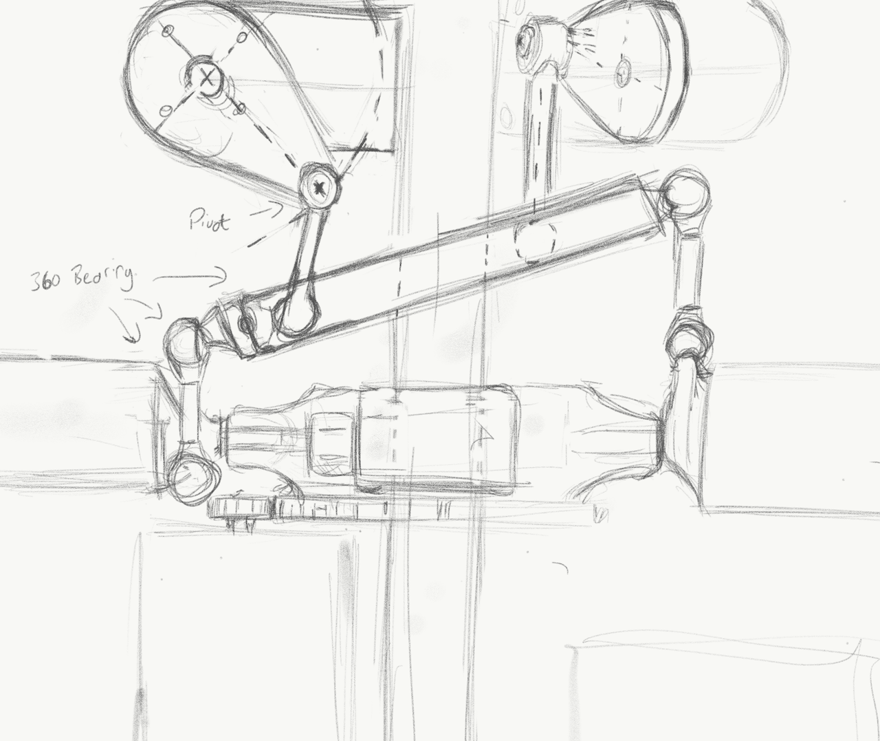
First: the idea. I sketched the basic layout and joints of how the interaction between the blades and the swash plate will work.
Now to the maths, how do we control the actuators?
Calculating Servo Angles
Our goal is to control the collective and cyclic by actuating the angle of each servo. We can determine which servo angles will allow the bearing to be in the current position using inverse kinematics. There are three servos. Each separated by . As there is only movement in the plane we can reduce the problem into the space and iterate over the different servos.
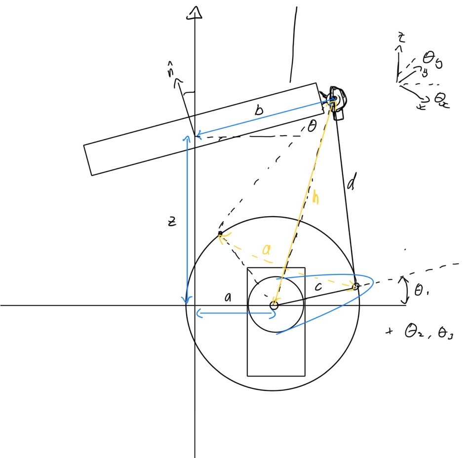
Our parameters are the placement of each component, in lengths:
- length of origin to servo
- length of bearing to joint
- length of servo to elbow, the servo arm
- length of elbow to joint
- length of origin to bearing, the height
Resolve the bearing angle to the 2D plane of the servo ().
Vectors of , bearing position, and , the servo position.
Distance between the two vectors.
Two circles are formed from the servo arm, , and length to the joint, . We find the distance to the intersection points and use that to determine the angle:
From the multiple intersections we are only concerned with outward facing one. Finally, resolving our angle back into our original reference frame, we get the servo angle:
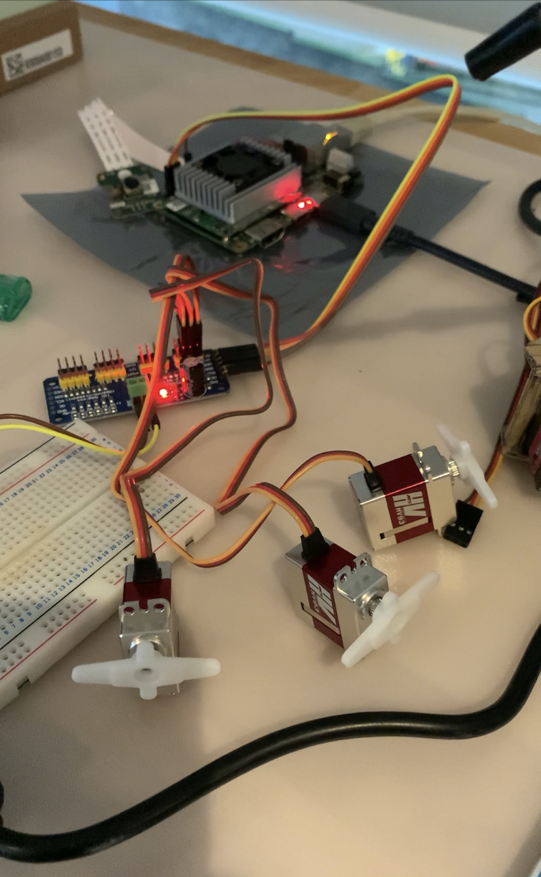
Testing
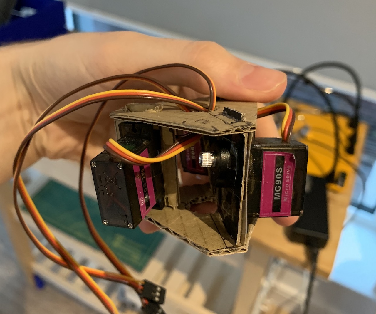
To test I setup a servo driver with a Beaglebone Blue. I built a cardboard setup, separating each servo by 120 degrees. From here I changed the length parameters to visualise the effects on the range of movements. This is something to optimise for in later revisions, but it works!
Future Work
Now my goal is to apply this to a proper RC model. I'm using the Google Coral AI board and some shiny new servos!